Difference between revisions of "Jenny corexy voron V1.2 mainpage"
Warriorlious (talk | contribs) (→check) |
Warriorlious (talk | contribs) |
||
| (41 intermediate revisions by the same user not shown) | |||
| Line 15: | Line 15: | ||
*[[BOM page]] | *[[BOM page]] | ||
*[https://grabcad.com/library/jennycorexy-3d-printer-v1-2-1 3d model] | *[https://grabcad.com/library/jennycorexy-3d-printer-v1-2-1 3d model] | ||
*[https://shop.jenny3dprint.com where to buy] | |||
==Communication== | ==Communication== | ||
*[ | *[https://discord.gg/TGurtFHg discuss] (trouble shooting and feature suggestions) | ||
*[ | *[https://www.facebook.com/groups/214755547287410 facebook] (assembly show and printing show) | ||
*[ | *[https://www.youtube.com/channel/UCNmPLRuaE8sS-DTZ5jvEpyw youtube] (Serial Request and development show) | ||
*[ | *[https://discord.gg/82Y9muqBBk discord] (timely communication) | ||
==Brief assembly instructions== | ==Brief assembly instructions== | ||
| Line 60: | Line 61: | ||
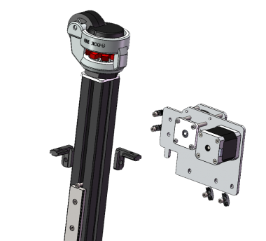
Two sets of symmetrical installation | Two sets of symmetrical installation | ||
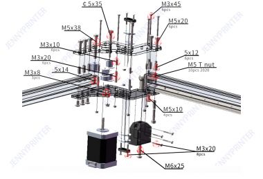
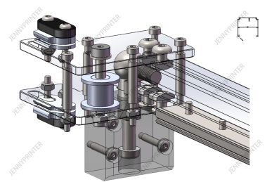
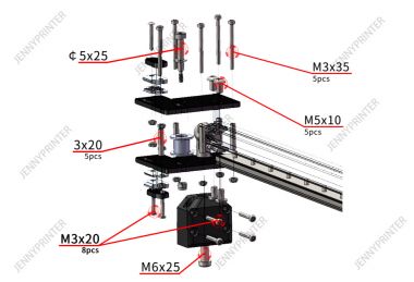
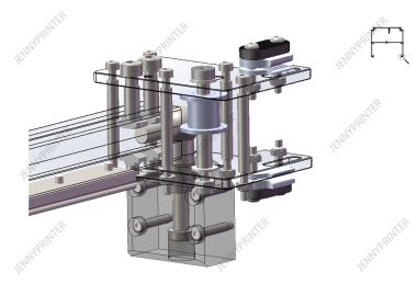
====top of 4Z Module==== | |||
{| class="wikitable" | |||
|+ bottom of Z Module | |||
|- | |||
! all !! detail | |||
|- | |||
| [[File:4z model overview.png|none|thumb|380x380px]]||[[File:Z bottom module.jpg|none|thumb|380x380px]] | |||
|} | |||
Make sure the motion resistance is minimal | |||
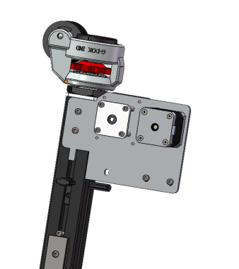
====top of 4Z Module ==== | |||
overview | overview | ||
[[File:4Z top.jpg|thumb|none|465x465px]] | [[File:4Z top.jpg|thumb|none|465x465px]] | ||
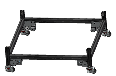
| Line 72: | Line 83: | ||
[[File:Assembly framework overview.png|thumb|none|501x501px]] | [[File:Assembly framework overview.png|thumb|none|501x501px]] | ||
Here M8 Screw down,used to install the castor. | |||
[[File:Z profile down.png|none|thumb|487x487px]] | |||
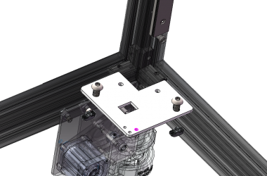
{| class="wikitable" | |||
|+ At the top of frame | |||
|- | |||
! Insert !! External screw !! Internal screw | |||
|- | |||
| [[File:Top of frame.png|thumb|none|380x380px]]||[[File:Top of frame 2.png|thumb|none|380x380px]] || [[File:Top of frame 3.png|thumb|none|380x380px]] | |||
|} | |||
{| class="wikitable" | |||
|+ Z rail | |||
|- | |||
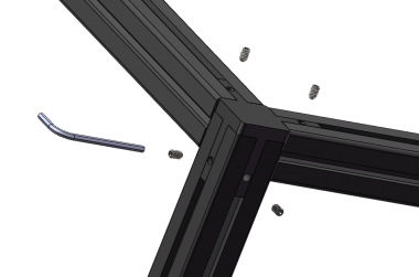
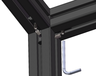
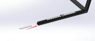
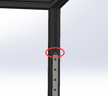
! Insert nut seat strips and use M4x12 screw !! use M6x25 and M6 T nut at end of rail !! Lock close to rail | |||
|- | |||
| [[File:Z rail nut seat.png|thumb|none|380x380pxpx]]||[[File:Zrail assembly.png|thumb|none|380x380pxpx]] || [[File:End of Z rail.png|thumb|none|380x380pxpx]] | |||
|} | |||
instert 2 fastener for every Z extrusion | |||
[[File:Fastener built-in instert before.png|thumb|none|494x494px]] | |||
{| class="wikitable" | |||
|+ castor | |||
|- | |||
! Insert spacer between castor and aluminum extrusion !! pay attention to direction of castor spacer | |||
|- | |||
| [[File:Castor spacer.png|thumb|none|380x380pxpx]]||[[File:Direction of castor spacer .png|thumb|none|380x380pxpx]] | |||
|} | |||
{| class="wikitable" | |||
|+ bottom of Z Module | |||
|- | |||
! Notice that it has been inserted fastener built-in !! Let z module lose to the castor spacer !! do it for all 4 corner and fixed cross extrusion | |||
|- | |||
| [[File:Fastener built-in instert.png|thumb|none|380x380pxpx]]||[[File:Bottom of Z module amb.png|thumb|none|380x380pxpx]]||[[File:Cross extrusion amb.png|thumb|none|380x380pxpx]] | |||
|} | |||
{| class="wikitable" | |||
|+ dead plate | |||
|- | |||
! use M8x16 !! do it for every corner | |||
|- | |||
| [[File:Z dead plate amb.png|thumb|none|380x380pxpx]]||[[File:Z dead plate amb 4 coner.png|thumb|none|380x380pxpx]] | |||
|} | |||
{| class="wikitable" | |||
|+ top z module | |||
|- | |||
! up z module !! pay attention to synchronous wheel angle alignment | |||
|- | |||
| [[File:Up z module amb.png|thumb|none|380x380px]]||[[File:Up z module angle alignment.png|thumb|none|380x380px]] | |||
|} | |||
===XY gantry Assembly=== | ===XY gantry Assembly=== | ||
{| | |||
[[File:XY gantry overview.png|thumb|none| | |- | ||
| [[File:XY gantry overview.png|thumb|none|400x400px]] || [[File:Jennycorexy V1.2 gantry.117.jpg|thumb|none|800x400px]] | |||
|} | |||
{| class="wikitable" | |||
|+ XY GANTRY | |||
|- | |||
! installed !! Break up | |||
|- | |||
| [[File:Jennycorexy v1.2 XY.2.1.jpg|thumb|none|380x380px]]|| [[File:Jennycorexy v1.2 XY 2.jpg|thumb|none|380x380px]] | |||
|- | |||
| [[File:Jennycorexy v1.2 XY.3.1.jpg|thumb|none|380x380px]]|| [[File:Jennycorexy v1.2 XY 3.jpg|thumb|none|380x380px]] | |||
|- | |||
| [[File:Jennycorexy v1.2 XY.4.1.jpg|thumb|none|380x380px]]|| [[File:Jennycorexy V1.2 XY 4.jpg|thumb|none|380x380px]] | |||
|- | |||
| [[File:Jennycorexy v1.2 XY.5.1.jpg|thumb|none|380x380px]]|| [[File:Jennycorexy V1.2 XY 5.jpg|thumb|none|380x380px]] | |||
|- | |||
| [[File:Jennycorexy v1.2 XY.6.1.jpg|thumb|none|380x380px]]|| [[File:Jennycorexy v1.2 XY 6.jpg|thumb|none|380x380px]] | |||
|- | |||
| [[File:Jennycorexy v1.2 XY.7.1.jpg|thumb|none|380x380px]]|| [[File:Jennycorexy v1.2 XY 7.jpg|thumb|none|380x380px]] | |||
|} | |||
===Belt installation (important step)=== | ===Belt installation (important step)=== | ||
====4Z Belt==== | ====4Z Belt==== | ||
Confirm top of z module’s adjust screw loosen.It is recommended to assemble Z belt before XY belt. | |||
[[File:Makesure top z module.png|thumb|none|495x495px]] | |||
====XY Belt==== | ====XY Belt==== | ||
{| class="wikitable" | |||
|+ XY BELT | |||
|- | |||
! A belt !! B belt | |||
|- | |||
| [[File:Jennycorexy V1.2 A belt.png|thumb|none|520x520px]]|| [[File:Jennycorexy V1.2 B belt.png|thumb|none|520x520px]] | |||
|} | |||
===Drawer Assembly=== | === Drawer Assembly=== | ||
overview | overview | ||
[[File:Drawer overview.png|thumb|none|502x502px]] | [[File:Drawer overview.png|thumb|none|502x502px]] | ||
| Line 101: | Line 201: | ||
get your ip | get your ip | ||
==check== | ===check=== | ||
{| class="wikitable" | {| class="wikitable" | ||
|[[File:Macros.png|thumb|none|513x513px]] | |[[File:Macros.png|thumb|none|513x513px]] | ||
|[[File:Controls.png|thumb|none|513x513px]] | |[[File:Controls.png|thumb|none|513x513px]] | ||
|} | |} | ||
*1.'''Endstop and probe check''' | * 1.'''Endstop and probe check''' | ||
Make sure that none of the X, Y, Z Endstops or probe are being pressed, and then click Macros EANDSTOPS&PROBE STATUS . The terminal window should respond with the following: | Make sure that none of the X, Y, Z Endstops or probe are being pressed, and then click Macros EANDSTOPS&PROBE STATUS . The terminal window should respond with the following: | ||
probe: TRIGGERED | probe: TRIGGERED | ||
| Line 112: | Line 212: | ||
If any of them say “triggered” instead of “open”, double check to make sure none of them are pressed. Next, manually press the X endstop, click Macros EANDSTOPS&PROBE STATUS again, and make sure that the X endstop says “triggered” and the Y and Z endstops stay open. Repeat with the Y and Z endstops.You may find that one of your Endstops has inverted logic (it displays “open” when it is pressed, and “triggered” when it is not). In this case, go to your printer’s config file and add or remove the ! In front of the pin. For instance, if your X endstop was inverted, you would add a ! In front of your pin numberas follows: | If any of them say “triggered” instead of “open”, double check to make sure none of them are pressed. Next, manually press the X endstop, click Macros EANDSTOPS&PROBE STATUS again, and make sure that the X endstop says “triggered” and the Y and Z endstops stay open. Repeat with the Y and Z endstops.You may find that one of your Endstops has inverted logic (it displays “open” when it is pressed, and “triggered” when it is not). In this case, go to your printer’s config file and add or remove the ! In front of the pin. For instance, if your X endstop was inverted, you would add a ! In front of your pin numberas follows: | ||
endstop_pin: PD12 —> !PD12 | endstop_pin: PD12 —> !PD12 | ||
*2.'''Separate motor check''' | *2.'''Separate motor check''' | ||
To verify that each stepper motor is operating correctly.click Macros TEST X、TEST Y、TEST Z0、TEST Z1、TEST Z2、TEST Z3 for every axis.Motors should go UP first then down. If the stepper motors do not move, check wiring for loose onnectors. | To verify that each stepper motor is operating correctly.click Macros TEST X、TEST Y、TEST Z0、TEST Z1、TEST Z2、TEST Z3 for every axis.Motors should go UP first then down. If the stepper motors do not move, check wiring for loose onnectors. | ||
*3.'''Print size and HOME check''' | * 3.'''Print size and HOME check''' | ||
open printer.cfg verify position_endstop and position_max value for your printer. | open printer.cfg verify position_endstop and position_max value for your printer. | ||
[stepper_x] | [stepper_x] | ||
| Line 135: | Line 235: | ||
position_endstop: 7 #modfiy this when nozzle changed.more small more far. | position_endstop: 7 #modfiy this when nozzle changed.more small more far. | ||
position_max: 512 | position_max: 512 | ||
... | |||
Click X and Y yellow bottom in Controls ,printhead HOME XY.Aand move printhead just above Z endstop's probe.the send M114,get current XY Position. | Click X and Y yellow bottom in Controls ,printhead HOME XY.Aand move printhead just above Z endstop's probe.the send M114,get current XY Position. | ||
| Line 141: | Line 242: | ||
[homing_override] | [homing_override] | ||
... | ... | ||
G0 X290 Y350 Z50 F4800 | G0 X290 Y350 Z50 F4800 | ||
*4.'''Mount probe position check''' | *4.'''Mount probe position check''' | ||
| Line 157: | Line 258: | ||
G1 X157 Y348 F3600; | G1 X157 Y348 F3600; | ||
G1 X249 Y348 F3600; | G1 X249 Y348 F3600; | ||
G1 X248 Y318 F3600; | G1 X248 Y318 F3600; | ||
*5.'''Gantry level point check''' | *5.'''Gantry level point check''' | ||
| Line 168: | Line 269: | ||
320,270 | 320,270 | ||
320,20 | 320,20 | ||
... | |||
* 6.'''Z 0 position check''' | |||
After do gantry level,move printhead in the middle of bed,and control Z to 0 position. The position_endstop in printer.cfg to control nozzle for or near to the bed . | |||
[stepper_z] | |||
... | ... | ||
position_endstop: 7 #modfiy this when nozzle changed.more small more far. | |||
[[printer.cfg(current)|printer.cfg]] reference | [[printer.cfg(current)|printer.cfg]] reference | ||
| Line 192: | Line 298: | ||
more info [https://github.com/KevinOConnor/klipper/blob/afca515e2c2db240b4d354a0ae665479894ef89b/docs/Config_checks.md Klipper PID calibrate]. | more info [https://github.com/KevinOConnor/klipper/blob/afca515e2c2db240b4d354a0ae665479894ef89b/docs/Config_checks.md Klipper PID calibrate]. | ||
---- | ---- | ||
====Calibrate extruder pressure ==== | ====Calibrate extruder pressure==== | ||
'''NOTE''':When you have send this part of the command,if you want to print another gcoode,restart 3d printer please. | '''NOTE''':When you have send this part of the command,if you want to print another gcoode,restart 3d printer please. | ||
* Prepare for the test by issuing the following G-Code command: | *Prepare for the test by issuing the following G-Code command: | ||
'''SET_VELOCITY_LIMIT SQUARE_CORNER_VELOCITY=1 ACCEL=500''' | '''SET_VELOCITY_LIMIT SQUARE_CORNER_VELOCITY=1 ACCEL=500''' | ||
| Line 205: | Line 311: | ||
*After that,print this gcode: [https://github.com/yzyyou/jenny-corexy-V1.2/blob/main/Docs/square_tower_test.gcode square_tower_test.gcode] | *After that,print this gcode: [https://github.com/yzyyou/jenny-corexy-V1.2/blob/main/Docs/square_tower_test.gcode square_tower_test.gcode] | ||
* The pressure_advance value can then be calculated as pressure_advance = <start> + <measured_height> * <factor>. (For example, 0 + 12.90 * .005 would be 0.0645.) | *The pressure_advance value can then be calculated as pressure_advance = <start> + <measured_height> * <factor>. (For example, 0 + 12.90 * .005 would be 0.0645.) | ||
Insert pressure_advance value in printer.cfg. | Insert pressure_advance value in printer.cfg. | ||
| Line 215: | Line 321: | ||
====Resonance compensation==== | ====Resonance compensation==== | ||
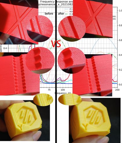
After do this step,you can get this effect: | After do this step,you can get this effect: | ||
[[File:Elimination_of_mechanical_resonance_1.jpg|thumb|left]] | [[File:Elimination_of_mechanical_resonance_1.jpg|thumb|left|491x491px]] | ||
'''NOTE''':When you have send this part of the command,if you want to print another gcoode,restart 3d printer please. | '''NOTE''':When you have send this part of the command,if you want to print another gcoode,restart 3d printer please. | ||
| Line 221: | Line 327: | ||
in section [printer]: | in section [printer]: | ||
max_accel : 7000 | max_accel : 7000 | ||
max_accel_to_decel : 7000 | max_accel_to_decel : 7000 | ||
*Disable Pressure Advance: | * Disable Pressure Advance: | ||
SET_PRESSURE_ADVANCE ADVANCE=0 | SET_PRESSURE_ADVANCE ADVANCE=0 | ||
* execute command: | *execute command: | ||
SET_INPUT_SHAPER SHAPER_FREQ_X=0 SHAPER_FREQ_Y=0 | SET_INPUT_SHAPER SHAPER_FREQ_X=0 SHAPER_FREQ_Y=0 | ||
If you get "Unknown command" error, you can safely ignore it at this point and continue with the measurements. | If you get "Unknown command" error, you can safely ignore it at this point and continue with the measurements. | ||
| Line 260: | Line 366: | ||
measured length AC BD AD | measured length AC BD AD | ||
example AC=140.5 BD=140.1 AD=99.92 unit mm | example AC=140.5 BD=140.1 AD=99.92 unit mm | ||
*Set management value in print_start and clear in print_end | * Set management value in print_start and clear in print_end | ||
In PRINT_START: | In PRINT_START: | ||
SET_SKEW XY=140.5,140.1,99.92 | SET_SKEW XY=140.5,140.1,99.92 | ||
| Line 268: | Line 374: | ||
---- | ---- | ||
==== speed tune==== | ====speed tune==== | ||
Modify these speed values to make the printer faster while maintaining quality. | Modify these speed values to make the printer faster while maintaining quality. | ||
*In section [printer]: | * In section [printer]: | ||
max_velocity: 200 | max_velocity: 200 | ||
max_accel: 3200 | max_accel: 3200 | ||
| Line 278: | Line 384: | ||
*In section [stepper_n]: | *In section [stepper_n]: | ||
homing_speed: 130 | homing_speed: 130 | ||
*In section [extender]: | *In section [extender]: | ||
| Line 292: | Line 398: | ||
==shell (optional)== | ==shell (optional)== | ||
overview | overview | ||
[[File:Shell overview.jpg|thumb|none| | {| class="wikitable" | ||
|[[File:Shell overview.jpg|thumb|none|510x510px]] | |||
|[[File:Jennycorexy overview.112.jpg|none|thumb|510x510px]] | |||
|} | |||
Latest revision as of 10:30, 2 October 2021
Overview
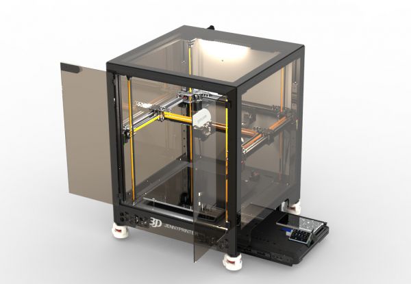
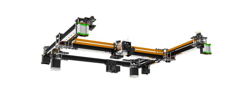
this is mainpage of jenny corexy 3d printer V1.2
jenny corexy is a metallized structure inspire by vorondesign voron2.4.
we use a more stable 4040 extrusions frame,but keep 2020 extrusions as gantry let it not too heavy. The gantry use a 9mm widened belt,to keep a bigger print size. Also expanded the width of the linear rails.
All structural part use aluminum sheet with stainless steel column let printer can stable in high temperature environment.But some of the beautiful parts that don't matter are whit 3D printed.
I also modified the leveling probe, using a structure I named JennyTouch. It is a contact type photoelectric sensor mechanism,can probe aluminum 、PEI、 glass and any solid platform.
Resources
Communication
- discuss (trouble shooting and feature suggestions)
- facebook (assembly show and printing show)
- youtube (Serial Request and development show)
- discord (timely communication)
Brief assembly instructions
WARNING
- The hot bed is powered by high-power 220V alternating current, pay attention to the protection of relevant connection points and avoid touching by human body when powered on.
- The motor drive module adopts aluminum heat sink, so do not touch the solder joint nearby when pasting and installing, so as to avoid burning the circuit.
- The mechanical installation part shall have pre-installation (incomplete screw tightening) step and final adjustment and locking (complete screw tightening) step.
- The belt of XY axis and 4Z has tensioning devices. When tensioning the belt at the initial stage of installation, the adjusting device should be adjusted in an adjustable state.
- Please confirm whether there is short circuit possibility, whether there is metal touching the main board, the driver module is inserted upside down, and the exposed wire ends are exposed, etc.
preparatory work
Recommended Tools
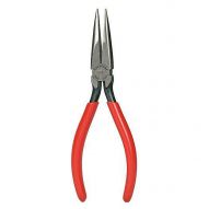
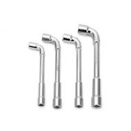
| Electric screwdriver | Torque screwdriver | Adjustable wrench | Long nose pliers | Sleeve Wrench(optional) |
The import of use torque screwdriver can read Screw Torque Specification
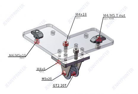
4Z module assembly
bottom of 4Z Module
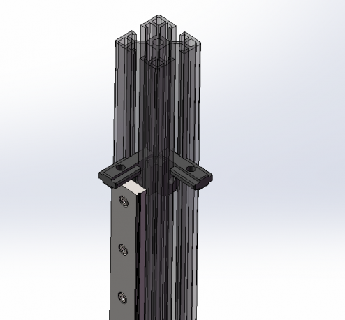
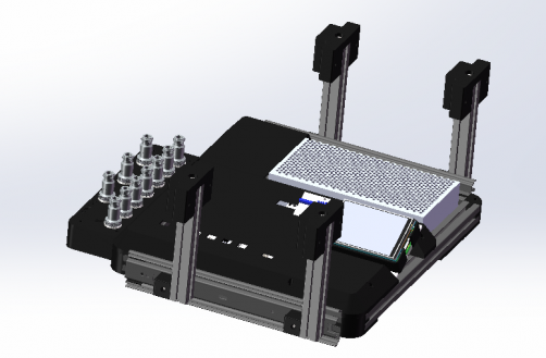
overview
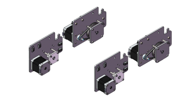
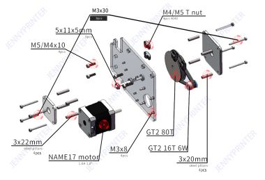
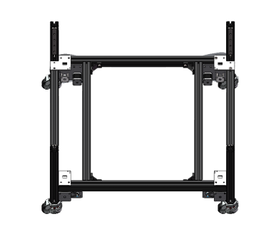
Two sets of symmetrical installation
| all | detail |
|---|---|
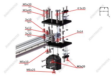
Make sure the motion resistance is minimal
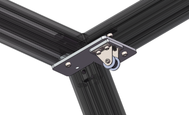
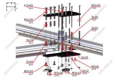
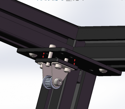
top of 4Z Module
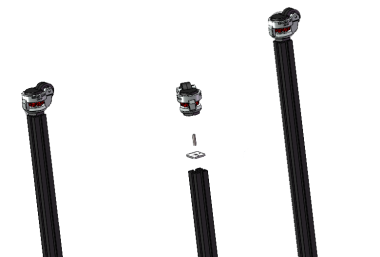
overview
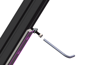
Note:M4x18 screw is used to adjust the belt, no need to install to locked
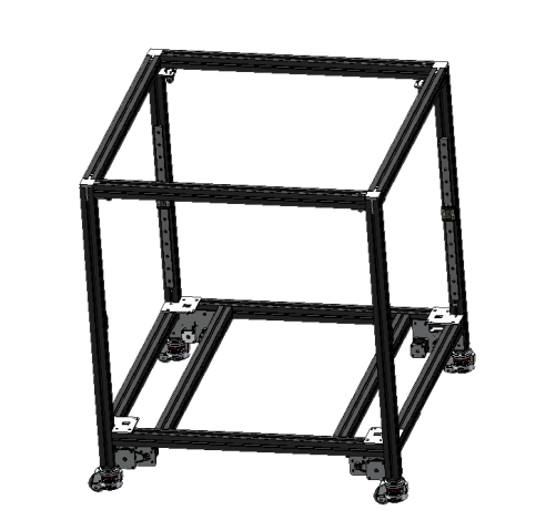
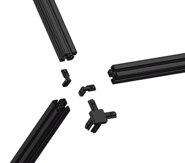
Framework Assembly
overview
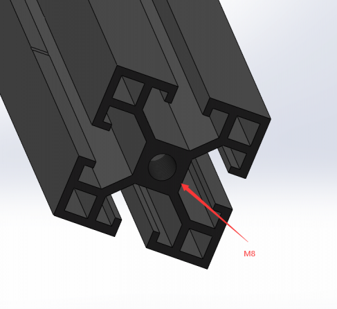
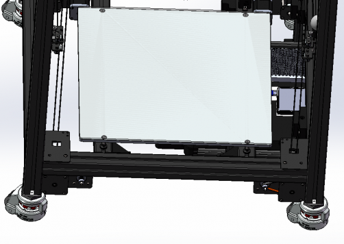
Here M8 Screw down,used to install the castor.
| Insert | External screw | Internal screw |
|---|---|---|
| Insert nut seat strips and use M4x12 screw | use M6x25 and M6 T nut at end of rail | Lock close to rail |
|---|---|---|
instert 2 fastener for every Z extrusion
| Insert spacer between castor and aluminum extrusion | pay attention to direction of castor spacer |
|---|---|
| Notice that it has been inserted fastener built-in | Let z module lose to the castor spacer | do it for all 4 corner and fixed cross extrusion |
|---|---|---|
| use M8x16 | do it for every corner |
|---|---|
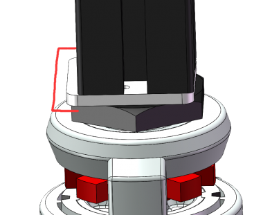
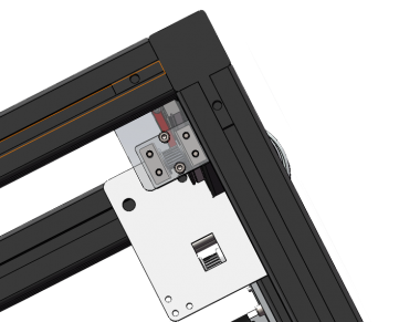
| up z module | pay attention to synchronous wheel angle alignment |
|---|---|
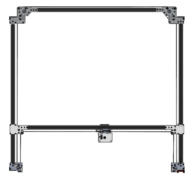
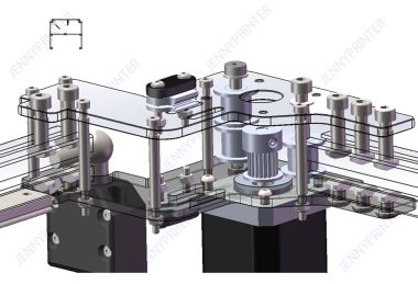
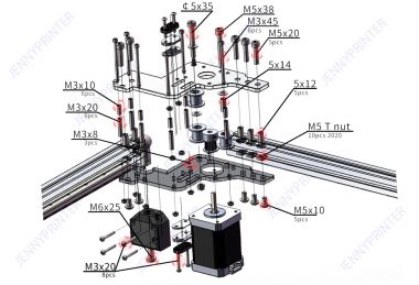
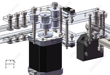
XY gantry Assembly
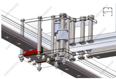
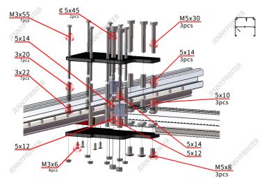
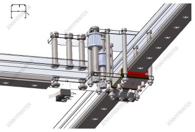
| installed | Break up |
|---|---|
Belt installation (important step)
4Z Belt
Confirm top of z module’s adjust screw loosen.It is recommended to assemble Z belt before XY belt.
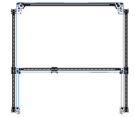
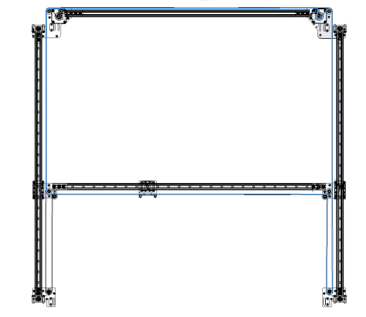
XY Belt
| A belt | B belt |
|---|---|
Drawer Assembly
overview
Bed Assembly
overview
ATTENTION:Let's say you have a shell,you must install bottom of the panel before this step.
Circuit wiring and installation
overview
setup firmware
get your ip
check
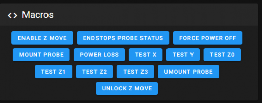
- 1.Endstop and probe check
Make sure that none of the X, Y, Z Endstops or probe are being pressed, and then click Macros EANDSTOPS&PROBE STATUS . The terminal window should respond with the following:
probe: TRIGGERED
x:open y:open z:open
If any of them say “triggered” instead of “open”, double check to make sure none of them are pressed. Next, manually press the X endstop, click Macros EANDSTOPS&PROBE STATUS again, and make sure that the X endstop says “triggered” and the Y and Z endstops stay open. Repeat with the Y and Z endstops.You may find that one of your Endstops has inverted logic (it displays “open” when it is pressed, and “triggered” when it is not). In this case, go to your printer’s config file and add or remove the ! In front of the pin. For instance, if your X endstop was inverted, you would add a ! In front of your pin numberas follows:
endstop_pin: PD12 —> !PD12
- 2.Separate motor check
To verify that each stepper motor is operating correctly.click Macros TEST X、TEST Y、TEST Z0、TEST Z1、TEST Z2、TEST Z3 for every axis.Motors should go UP first then down. If the stepper motors do not move, check wiring for loose onnectors.
- 3.Print size and HOME check
open printer.cfg verify position_endstop and position_max value for your printer.
[stepper_x]
...
position_endstop: 350
position_max: 350
...
[stepper_y]
...
position_endstop: 350
position_max: 350
...
[stepper_z]
...
position_endstop: 7 #modfiy this when nozzle changed.more small more far.
position_max: 512
...
Click X and Y yellow bottom in Controls ,printhead HOME XY.Aand move printhead just above Z endstop's probe.the send M114,get current XY Position.
X:290.00 Y:350.00 Z:20.00 E:0.00
Use this X290 Y350 value verify homing_override in printer.cfg:
[homing_override]
...
G0 X290 Y350 Z50  F4800
- 4.Mount probe position check
Click MOUNT PROBE bottom in Macros,printhead move to mount probe;click UMOUNT PROBE printhead move to unmount probe.the move action is define in printer.cfg
[gcode_macro MOUNT_PROBE]
gcode:
       G1 X249 Y318 F3600;
       G1 X249 Y348 F3600;
       G1 X157 Y348 F3600;
       G1 X157 Y318 F3600;
[gcode_macro UMOUNT_PROBE]
gcode:
       G1 X157 Y318 F3600;
       G1 X157 Y348 F3600;
       G1 X249 Y348 F3600;
       G1 X248 Y318 F3600;
- 5.Gantry level point check
Verify this 4 points in your printer.cfg,make sure that probe touch this 4 points are in corner of bed ,and nothing will stand in the way.
[quad_gantry_level]
...
points:
       30,20
       30,270
       320,270
       320,20
...
- 6.Z 0 position check
After do gantry level,move printhead in the middle of bed,and control Z to 0 position. The position_endstop in printer.cfg to control nozzle for or near to the bed .
[stepper_z]
...
position_endstop: 7 #modfiy this when nozzle changed.more small more far.
printer.cfg reference
Debugging
PID
use this command to calibrate hotend pid:
PID_CALIBRATE HEATER=extruder TARGET=220
And this command to calibrate bed pid:
PID_CALIBRATE HEATER=heater_bed TARGET=60
when finished will have some information like this:
PID parameters: pid_Kp=18.731 pid_Ki=0.827 pid_Kd=106.065 The SAVE_CONFIG command will update the printer config file with these parameters and restart the printer.
Use this PID value in printer.cfg
more info Klipper PID calibrate.
Calibrate extruder pressure
NOTE:When you have send this part of the command,if you want to print another gcoode,restart 3d printer please.
- Prepare for the test by issuing the following G-Code command:
SET_VELOCITY_LIMIT SQUARE_CORNER_VELOCITY=1 ACCEL=500
- This command makes the nozzle travel slower through corners to emphasize the effects of extruder pressure. Then for printers with a direct drive extruder run the command:
TUNING_TOWER COMMAND=SET_PRESSURE_ADVANCE PARAMETER=ADVANCE START=0 FACTOR=0.005
- After that,print this gcode: square_tower_test.gcode
- The pressure_advance value can then be calculated as pressure_advance = <start> + <measured_height> * <factor>. (For example, 0 + 12.90 * .005 would be 0.0645.)
Insert pressure_advance value in printer.cfg.
JENNY COREXY BGM extuder pressure_advance = 0.046 about.
more info Klipper pressure
Resonance compensation
After do this step,you can get this effect:
NOTE:When you have send this part of the command,if you want to print another gcoode,restart 3d printer please.
- Increase max_accel and max_accel_to_decel parameters in your printer.cfg to 7000. remember save config and restart firmware.
in section [printer]:
  max_accel : 7000
  max_accel_to_decel : 7000
- Disable Pressure Advance:
SET_PRESSURE_ADVANCE ADVANCE=0
- execute command:
SET_INPUT_SHAPER SHAPER_FREQ_X=0 SHAPER_FREQ_Y=0
If you get "Unknown command" error, you can safely ignore it at this point and continue with the measurements.
- execute command:
SET_INPUT_SHAPER SHAPER_TYPE=MZV
- Execute the command:
TUNING_TOWER COMMAND=SET_VELOCITY_LIMIT PARAMETER=ACCEL START=1250 FACTOR=100 BAND=5
This command will increase the acceleration every 5 mm starting from 1500 mm/sec^2: 1500 mm/sec^2, 2000 mm/sec^2, 2500 mm/sec^2 and so forth up until 7000 mm/sec^2 at the last band.
- Print this ringing_tower_test.gcode
This PLA filament 0.4mm nozzle used in gcode.
- stop the print earlier or wait for the result
You can stop the print earlier if the ringing is clearly visible and you see that acceleration gets too high for your printer (e.g. printer shakes too much or starts skipping steps)
- Measurement and calculation
- Save parameter in printer.cfg
in section [input_shaper]:
  shaper_freq_x: ...
  shaper_freq_y: ...
  shaper_type: mzv
- Revert the changes to max_accel and max_accel_to_decel parameters
After finishing this Resonance compensation do not forget revert change this in printer.cfg
more info Resonance_Compensation
Use ADXL345 accelerometer Measuring_Resonances This also can measurement the XY max_accel.
Skew correction
- Add a section [skew_correction] in print.cfg
[skew_correction]
print this Skew_correction_test.gcode
- Take your measurements
measured length AC BD AD
example AC=140.5 BD=140.1 AD=99.92 unit mm
- Set management value in print_start and clear in print_end
In PRINT_START:
SET_SKEW XY=140.5,140.1,99.92
In PRINT_END:
SET_SKEW CLEAR=1
more info skew_correction
speed tune
Modify these speed values to make the printer faster while maintaining quality.
- In section [printer]:
  max_velocity: 200
  max_accel: 3200
  max_z_velocity: 10
  max_z_accel: 200
- In section [stepper_n]:
homing_speed: 130
- In section [extender]:
  max_extrude_only_velocity:100
  max_extrude_only_accel:3000
- in section [probe]:
speed: 80.0
- In section [quad_gantry_level]:
speed: 120
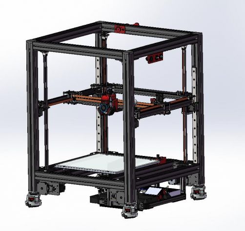
shell (optional)
overview
